উত্তরঃ
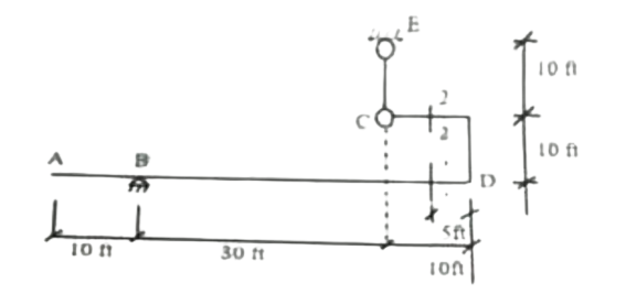
The structure shown in the figure is a statically indeterminate frame connected to a beam. To draw influence lines for such a structure, Müller-Breslau's Principle is typically used to determine the qualitative shape, and advanced structural analysis methods (like the Flexibility Method or Stiffness Method) are employed to calculate the precise ordinates at various points for quantitative analysis. Given the complexity and the request to "draw," the answer will focus on describing the application of Müller-Breslau's Principle and the qualitative shape of each influence line, along with the method for determining key ordinates.
Structural Interpretation:
- The main horizontal beam runs from A to D.
- A is a free end (cantilevered).
- B is a roller support, located 10 ft from A.
- C is a joint on the beam, 30 ft from B. From C, a vertical member C-E of 20 ft (10 ft + 10 ft) rises to a fixed support at E.
- D is a joint on the beam, 10 ft from C. At D, a frame element extends downwards 5 ft, then horizontally 10 ft, and then up. This part of the frame provides significant stiffness and support to the main beam at D.
- Section 1-1 is located between B and C.
- Section 2-2 is located between C and D.
Influence Line for Ra (Reaction at A)
As per the provided diagram, point A is shown as a free end of the beam with no support symbol. Therefore, there is no reaction force (Ra) at point A. The influence line for Ra would be a horizontal line at zero for all positions of the unit load from A to D.
In structural analysis, reactions only occur at points of support. Since A is depicted as a free end, it cannot develop a reaction force. If the question intended Ra to mean the reaction at support B (RB), then the influence line would be different (as described below for RB, if applicable).
Influence Line for RB (Vertical Reaction at B - assuming Ra was a typo for RB)
If Ra was intended to be the vertical reaction at roller support B (RB):
Müller-Breslau Principle Application: To obtain the influence line for RB, remove the roller support at B and apply a unit vertical displacement upwards at B. The deflected shape of the structure will represent the influence line for RB.
Qualitative Shape:
- The influence line will be a continuous curve, starting from an ordinate at A (which is a free end, so a unit load at A would induce a reaction at B).
- It will have an ordinate of 1.0 directly at B (the point of applied unit displacement).
- The curve will then extend towards D, generally positive but decreasing, influenced by the stiffness provided by the fixed support at E and the frame at D.
- Due to the fixed support at E and the stiff frame at D, the beam will deflect significantly, and the influence line ordinates will be smooth and continuous, reflecting the indeterminate nature.
Key Ordinates: The ordinate at B is 1.0. Other critical ordinates (e.g., at A, C, D) would need to be calculated by applying a unit load at these respective points and solving the indeterminate structure (e.g., using the Stiffness Method) to find RB.
Influence Line for V1-1 (Shear at Section 1-1)
Müller-Breslau Principle Application: To obtain the influence line for shear at section 1-1 (located between B and C), cut the beam at section 1-1 and apply a unit relative vertical displacement (shear distortion). This is achieved by displacing the left segment (from A to 1-1) downwards by 0.5 unit and the right segment (from 1-1 to D) upwards by 0.5 unit, ensuring no relative rotation occurs at the cut section. The deflected shape of the structure will be the influence line for V1-1.
Qualitative Shape:
- The influence line will be a continuous curve.
- It will generally be negative when the unit load is to the left of section 1-1 and positive when the unit load is to the right.
- There will be a 'shear jump' or discontinuity in ordinates at section 1-1, where the value transitions from negative to positive. The magnitude of this jump, in a statically indeterminate structure, is influenced by the structural stiffness.
- The influence line shape will reflect the stiffening effects of the roller support at B, the fixed support at E, and the frame at D.
Key Ordinates: The exact ordinates at critical points (e.g., A, B, C, D, and immediately to the left and right of section 1-1) would be computed by applying a unit load at each point and performing a detailed structural analysis to determine the shear force at section 1-1.
Influence Line for M1-1 (Moment at Section 1-1)
Müller-Breslau Principle Application: To obtain the influence line for bending moment at section 1-1 (between B and C), introduce an internal hinge at section 1-1. Then, apply a unit relative rotation at this hinge. The resulting deflected shape of the structure will represent the influence line for M1-1.
Qualitative Shape:
- The influence line will be a continuous curve with a distinct "kink" (change in slope) at section 1-1, which is the point where the unit relative rotation was applied.
- The ordinates can be positive or negative depending on the load position and the overall structural behavior.
- Near section 1-1, the ordinates will likely be positive, causing tension at the bottom fiber. As the unit load moves towards the fixed support at E or the stiff frame at D, significant negative moments (tension at the top fiber) are expected.
Key Ordinates: Exact ordinates at key points (A, B, C, D, and section 1-1) are obtained by placing a unit load at these points and solving the indeterminate structure for the bending moment at section 1-1.
Influence Line for V2-2 (Shear at Section 2-2)
Müller-Breslau Principle Application: Similar to V1-1, to obtain the influence line for shear at section 2-2 (located between C and D), cut the beam at section 2-2 and apply a unit relative vertical displacement (shear distortion), maintaining zero relative rotation. The deflected shape will be the influence line for V2-2.
Qualitative Shape:
- The influence line will be a continuous curve.
- It will generally show negative ordinates when the unit load is to the left of section 2-2 and positive ordinates when to the right.
- A 'shear jump' will occur at section 2-2.
- The shape will be significantly influenced by the rigid connections at C and D, the fixed support at E, and the overall frame action, leading to a smooth, continuous curve on either side of the cut.
Key Ordinates: Calculating exact ordinates requires applying a unit load at various points and solving the indeterminate frame to find the shear force at section 2-2.
Influence Line for M2-2 (Moment at Section 2-2)
Müller-Breslau Principle Application: Similar to M1-1, to obtain the influence line for bending moment at section 2-2 (between C and D), introduce an internal hinge at section 2-2. Then, apply a unit relative rotation at this hinge. The resulting deflected shape of the structure will represent the influence line for M2-2.
Qualitative Shape:
- The influence line will be a continuous curve with a distinct "kink" (change in slope) at section 2-2.
- Being in the segment C-D, which is part of the rigid frame, the moment influence line will exhibit complex behavior.
- Due to the fixed support at E and the frame action, there will likely be significant negative moment ordinates when the load is far from section 2-2, and positive ordinates when the load is closer to the section.
Key Ordinates: Exact ordinates at key points (A, B, C, D, and section 2-2) are obtained by placing a unit load at these points and solving the indeterminate structure for the bending moment at section 2-2.
For a detailed "drawing" of these influence lines with precise numerical ordinates, specialized structural analysis software or a laborious manual calculation using methods like the slope-deflection method, moment distribution method, or matrix methods (stiffness/flexibility) would be required due to the high degree of indeterminacy of the combined beam-frame structure.